Category: Arduino

Working house monitor

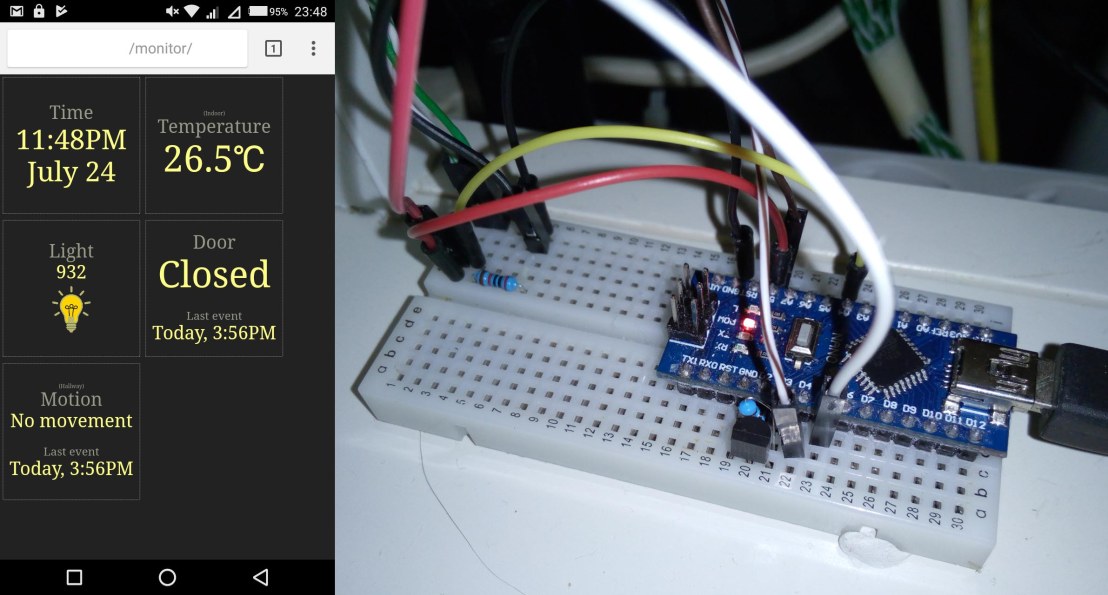
For some time now my house monitor circuit has been working and logging data as well as providing a web interface where the current status of the sensors can be seen. Not that many sensors right now but;

  • Door sensor. Simple aluminium foil pads in the doorframe wired such that if the door is closed, the input pin is directly connected to ground. If the door opens, the connection is broken and through a 5k resistor, the pin is pulled up to +5V.
  • Motion sensor pointed at my hallway and door. To see when people come and go, as well as seeing when I visit the toilet and such… there is no such thing as too much information…
  • Photoresistor underneath my desk lamp. Any time Im at my desk, my desk lamp is lit, so its an indication of wether Im at my desk or not.
  • Dallas 18B20 temperature sensor. Next to my desk (but one shelf up above a server so its constantly reading a bit hotter than the rest of the room).

In the future I hope to expand the system with wires to my window for reading outside temperature and light.

And I have to work on making graphs for trends over the course of a day, month or year for temperature and light sensor readings.

housemonitor1

OneWire circuit

So I’m having thoughts of wiring my house with a bunch of sensors but would like to limit the amount of wires as much as possible. Ofcourse that would best be done with some kind of OneWire circuit. One wire for ground and one wire for data and power.

I’ve experimented in Falstad’s circuit emulator and so far this is what I’ve come up with.

fiacrop1

The 470uF capacitor keeps the remote circuit (here its just a 1k resistor) powered while the data line (A) is pulled to ground to send signals. The resistor-transistor at the power source limits the current so it won’t short-circuit. The switch will be replaced with a MCU of some sort to control the sending of data.

I’m thinking of CLR, DATA and CLK going into a 74HC164 serial-to-parallel chip. Pulling the data wire (A) to ground very briefly would latch a 1 (one) as CLK goes back high, pulling it to ground a little bit longer would drain the 4.7uF capacitor enough to register a 0 (zero) when CLK goes high and finally pulling the wire to ground long enough to drain the 10uF capacitor would make CLR go low and reset the HC164 (asynchronous active low).

Timing depends on the values of the capacitors. Ofcourse at point (B) the voltage to power the MCU would be only 3V, but an atmega or attiny will run on that. It’s even possible to have several sensor circuits on the same two wires.

Now I just have to go from drawingboard to physical circuit and make it work…

Chinese chip connection…

“Psst. Hey dude. Over here…”

A chinese man in the shadows beckons me to come over. When I do, he opens his coat to show me the lining covered with little bags full of INTEGRATED LOGIC CIRCUITS.

The mans name is Ali. Ali Express. And while he claims his goods are the best, straight from the factory, it can sometimes be something entirely different. But, most of the time it gets the job done.

Ali has been my supplier for a while now. Sometimes his wares are scruffy but it’s usually not an outright disappointment.

Today he dropped another small bag at our secret drop box. It was filled with… well, see for yourself. Plastic cases or foam was not included ofcourse. Alis wares usually comes wrapped in horrible kitchen plastic foil. Cringeworthy stuff having near static sensitive devices. But hey, it’s cheap.

All of this for 11 dollars, 13 cents. Shipping included. But Ali made a mistake this time, I only ordered and paid for 2x ATTINY85s, but I received 5x.

My uncle also dropped by today and left a few (three) PIC16C84-04/P chips as well. So now I’m all set up with MCUs for a while. No more excuses, it’s time to get around to doing something useful…

chipgood1

Optimizing the LedControl library

vlcsnap-2017-02-05-23h54m51s351.png

After hooking up eight LED matrices in series, I could see that the LedControl library wasnt up to the task. After digging through the source code I realized what a peice of junk it was.

I had to do better myself. And did. I even ended up writing my new routine in assembler. Better optimized than even the code gcc managed to produce.

Source code in the form of an Atmel Studio project,
is available here: http://joonicks.eu/arduino/LedControl.zip